


Tortai strictly in accordance with the IPC standard control, to ensure that the shipment quality pass rate, such as customers in the specification of the use of products in the process of non-PCB external factors lead to bad problems. All PCB circuit boards undergo strict inspection, in addition to manual visual inspection, we use automatic testing, testing equipment, such as AOI optical inspection, FAI first piece inspection, X-ray inspection, ICT test, DIP plug-in AOI test, aging test, PCBA function test, program burning, electrical performance test, FCT function test and other equipment.
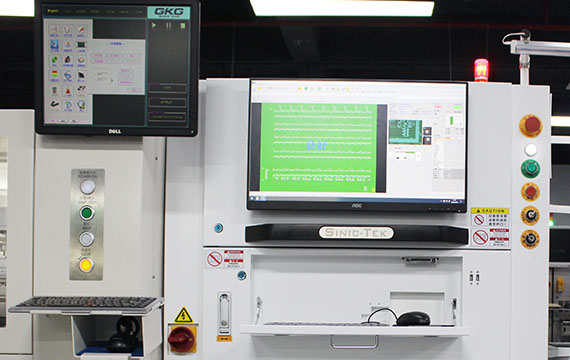
Solder Paste Inspection (SPI)
for-SMT.jpg)
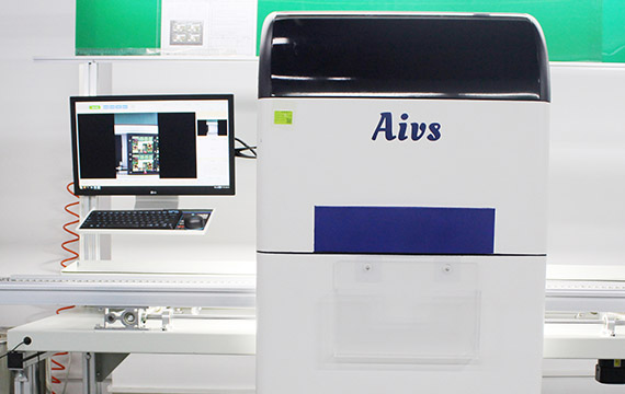
Auto Optical Inspection (AOI)for SMT
First Article Inspection (FAI)

In-Circuit Test (ICT)

X-Ray Testing
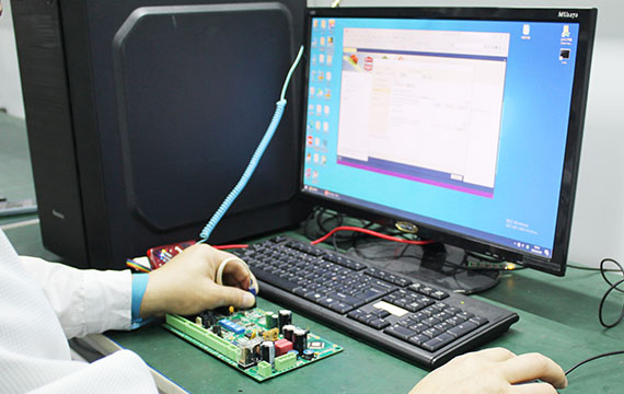
Function Testing(FCT)
AOI for DIP
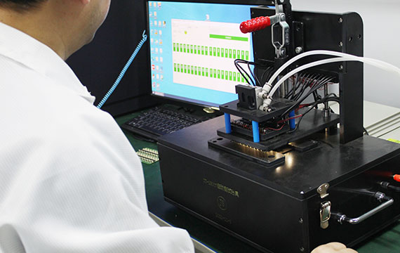
PCBA Programme Burning
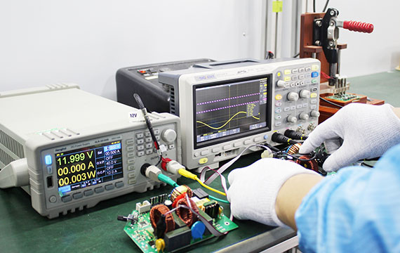
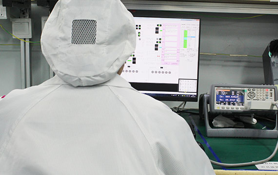
PCBA Electric Performance Testing
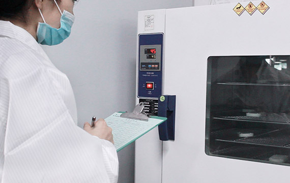
PCBA Aging Test
10 Products Found.