


Controlled error-proofing makes it impossible for errors to occur, i.e. the role of prevention, e.g. the example of setting railings at junctions mentioned above; it also makes it impossible for defective products to flow to the next link, playing the role of detection, e.g.: lifts stop running when they are overloaded and cannot go up or down.

Warning type error prevention, when the error is about to happen to give a preventive warning, but also can play a preventive role, for example, car reversing radar will be a certain distance from the obstacle will be sounded; also can give a warning when the error has already occurred, to play a detective role. For example: a lift will sound if it is overloaded, a smoke detector will sound an alarm if there is smoke in the house.

There are three main methods of prevention and detection that we normally use. The first is the contact method, where errors are detected by things coming into contact with each other and being found to not match after contact. For example, in a socket with three jacks, in order to ensure that the plugs of various electrical appliances are inserted with the correct polarity, the jack positions are designed to be error-proof, so that only the plugs are aligned with the corresponding holes before they can be inserted.

The second is called the quantitative method, which means that an error is detected when a certain job does not reach a fixed quantity. For example, if we put all the parts needed for a process in a box and, on completion, if we find that there are parts left in the box, that would indicate an omission. The form trace management we use on site falls under this method.
The third is the sequential method, which involves working in a fixed order and detecting errors if there are interruptions. For example, the final assembly of a hard drive requires 7 different screws to be fitted. To prevent the screws from being missed, the seven screws can be packed in a box with seven compartments and sealed in the order of assembly. When assembling, the seal has to be removed to access the screws. Therefore, if the seal has not been removed, it means that there are still screws left to be assembled and it will soon be possible to find out where they have been missed.

When designing error-proof devices, the following ten principles are generally followed:
1. The root cause principle: the cause of the error will be eliminated from the root cause so that it never occurs.
2. Insurance principle: more than two actions are needed to complete the work together or in sequence.
3. Automatic principle: the use of various optical, electrical, mechanical, mechanical, chemical and other principles to limit the execution or non-execution of certain actions in order to avoid errors.
4. Conformity principle: to prevent errors from occurring by checking for conformity of actions.
5. Sequence principle: to avoid reversing the working order or process, and to reduce or avoid errors by arranging them in a numbered sequence.
6. Isolation principle: by separating different areas, to achieve the protection of certain important parts, so that they can not cause danger or error.
7. Layer principle: to avoid making mistakes in different jobs and trying to distinguish them.
8. Duplication principle: If you need to do the same job more than twice, it is better to use the “duplication” method to save time and prevent mistakes.
9. Warning principle: If abnormal phenomena occur, various “warning” signals can be displayed by sound, light or other means to avoid errors.
10. Mitigation principle: to protect the method to reduce the damage caused by the error, although it can not completely exclude the error, but can reduce the degree of its return.

Specifically in the implementation, we have to refer to the following types of ways to flexibly apply in conjunction with the actual situation on site.
1. Mould and fixture error prevention: a) abnormal parts cannot be installed; b) no action in the mould when parts are misplaced; c) parts cannot be removed from the mould or fixture when there is an operational error or an error in the workflow.
2. Error prevention for machinery and equipment: a) machinery and equipment stop working when an abnormality occurs during processing; b) machinery and equipment cannot start when there is an operational error or an error in the workflow; c) subsequent machinery and equipment do not operate when a process is forgotten; d) sensors automatically identify defective products.
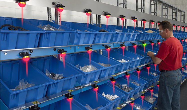
3. Error-proofing of devices and markings: a) red light alarm in the event of a fault; b) buzzer alarm in the event of a fault; c) different colours or labels to distinguish the place where the parts are placed.
4. Error-proofing of operating conditions: when operating conditions (e.g. voltage, current, pressure, time, etc.) have an abnormal effect on the results, machinery and equipment stop working.
5. Error-proofing of the design structure: e.g. adding process holes, error-proof holes, etc.
From the above examples, we can see that the use of different error prevention techniques to achieve the effect is not the same. We generally divide them into three levels, the first level is to be able to achieve the effect of preventing the occurrence of errors, that is, to prevent the occurrence of errors from the source, which will not lead to defects; the second level is to be able to detect errors immediately after they occur, so as not to lead to defects; the third level is to be able to detect defects immediately after they occur, that is, after errors lead to defects, we can immediately detect them and bring the defects to the The third level is that defects can be detected immediately after they occur, meaning that we can detect them immediately after they have occurred and minimise the damage they cause. We advocate the first level of error prevention, i.e. source control.