


With the development of electronic technology, electronic components towards miniaturisation and high density integration of the direction of development, BGA components have been more and more widely used in SMT assembly technology, and with the emergence of u BGA and CSP, the difficulty of SMT assembly is more and more difficult, the process requirements are also more and more high. Because of the difficulty of BGA rework is quite large, so to achieve good soldering of BGA is placed on all SMT engineering staff of a subject. Here on the BGA preservation and use of the environment and soldering process and other two major aspects of the discussion with you.
The Preservation And Use of BGA
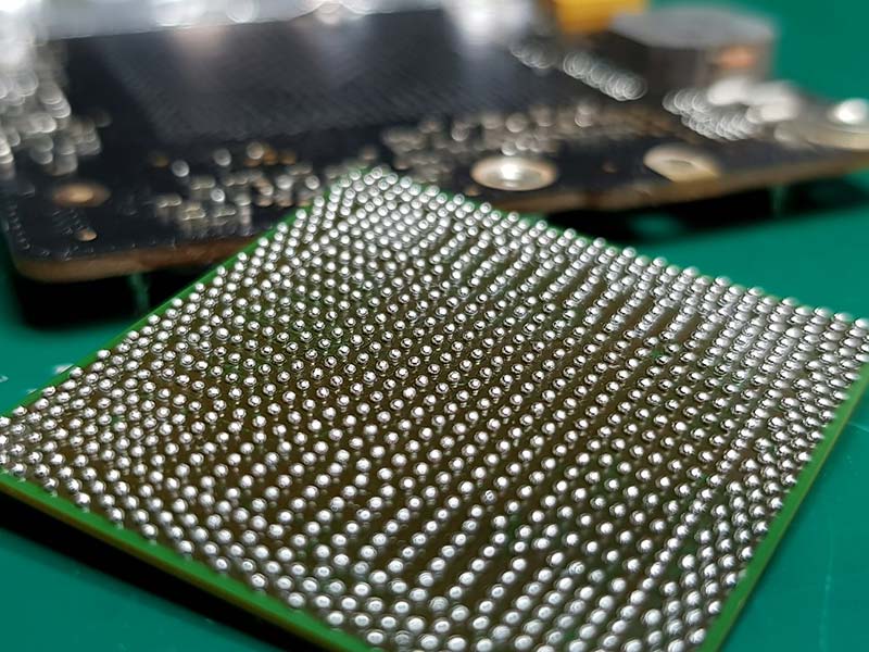
BGA components is a highly temperature-sensitive components, so BGA must be preserved in a constant temperature and dry conditions, the operator should strictly comply with the operating procedures to avoid components in the assembly before the impact. Generally speaking, the ideal preservation environment for BGA is 200C-250C, with humidity less than 10% RH (nitrogen protection is better).
In most cases, we will pay attention to the moisture-proof treatment of BGAs before the packaging of components is opened, and we should also pay attention to the time that the components should not be exposed after the packaging has been hit for the process of installation and soldering, in order to prevent the components from being affected by the degradation of the quality of soldering or the change of the electrical properties of the components. The following table is a classification of humidity-sensitive grades, which shows the corresponding time that components must be used for mounting and soldering once the sealed moisture-proof package has been opened during the assembly process. Generally speaking, BGAs belong to the humidity sensitivity class of 5 or higher.
Table 1 Moisture Sensitivity Classes.
| Grade | Time | Time |
| 1 | Unlimited | ≤30ºC/85% RH |
| 2 | Year | ≤30ºC/60% RH |
| 2a | All around | ≤30ºC/60% RH |
| 3 | 168 hours | ≤30ºC/60% RH |
| 4 | 72 hours | ≤30ºC/60% RH |
| 5 | 48 hours | ≤30ºC/60% RH |
| 5a | 24 hours | ≤30ºC/60% RH |
| 6 | By Labelling Time Regulations | ≤30ºC/60% RH |
If the components are stored under nitrogen conditions, then the time of use can be relatively extended. Approximately every 4-5 hours of dry nitrogen action extends the air exposure time by 1 hour.
During the assembly process we often encounter situations where components are opened in packages that cannot be used within the corresponding time and the exposure time exceeds the time specified in Table 1, then before the next use we recommend baking the BGA components in order to give the components good solderability. Baking conditions: temperature of 1250C, relative humidity ≤ 60% RH, baking time refer to Table 2.
Baking temperature should not exceed 125 ℃, because too high a temperature will cause the tin ball and components connected to the metallurgical organisation changes, and when these components into the reflow stage, easy to cause the tin ball and components package at the disconnection, resulting in the quality of the SMT assembly problems, but we will think that it is the quality of the components themselves caused by the problem. However, if the baking temperature is too low, it will not be able to play the role of dehumidification. If conditions permit, we recommend baking the components before assembly, which is conducive to eliminating the internal moisture of the BGA, and to improve the heat resistance of the BGA, reducing the components into the reflow soldering thermal shock on the device.BGA components are removed after baking, and then naturally cooled for half an hour before assembly.
Table 2 Baking Time
| Encapsulation Thickness | Humidity sensitivity class | Baking time |
| ≤1.4MM | 2a | 4 hours |
| 3 | 7 hours | |
| 4 | 9 hours | |
| 5 | 10 hours | |
| 5a | 14 hours | |
| ≤2.0MM | 2a | 18 hours |
| 3 | 24 hours | |
| 3 | 31 hours | |
| 5a | 37 hours | |
| ≤4.0MM | 2a | 48 hours |
| 3 | 48 hours | |
| 3 | 48 hours | |
| 3 | 48 hours | |
| 5a | 48 hours |
Soldering Process Requirements for BGA
In the assembly process of BGA, every step and every tool will have an impact on the soldering of BGA.
1、Solder Paste Printing
The advantages and disadvantages of solder paste are an important part of surface mount production. Selection of solder paste will usually consider the following aspects: good printability, good solderability, good solderability and low residue. In general, we use solder paste alloy composition of 63% tin and 37% lead with low residue type solder paste.
Table 3 shows how to select the appropriate solder paste according to the component’s pin spacing. From the table can be seen between the pins of the components of the more ingenious, the solder paste the smaller the tin powder particles, relatively speaking, the printing is better. But it does not mean that the choice of solder paste the smaller the better, because from the soldering effect, the soldering effect of the solder paste with large particles of tin powder than the solder paste with small particles of tin powder. Therefore, we have to choose from all aspects of the factors to be considered. Due to the BGA pin-to-pin is small, the screen stencil opening is small, so we use the diameter of 45M below the solder paste to ensure that we get good printing results.
Table 3 Solder Paste Powder Shape and Particle Diameter
| Pin Spacing (MM) | 1.27 | 1 | 0.8 | 0.65 | 0.5 | 0.4 |
| Tin Powder Shape | Non spherical | Spherical | Spherical | Spherical | ||
| Particle diameter (um) | 22-63 | 22-63 | 22-63 | 22-38 | ||
The screen stencils for printing are generally made of stainless steel. Due to the small pin spacing of BGA components, so the thickness of the steel plate is thin. The general thickness of the steel plate is 0.12MM-0.15MM. the opening of the steel plate depends on the component, usually the opening of the steel plate is slightly smaller than the pad.
For example: the external size of 35MM, between the pins of a unique 1.0MM PBGA, solder rib diameter of 23MIL, we generally control the size of the opening of the steel plate in 21MIL.
When printing, usually use stainless steel 60 degrees metal scraper. The printing pressure is controlled within the range of 3.5KG-10KG. Too much or too little pressure is not good for printing. Printing speed control in the 10MM/SEC-25MM/SEC between, the smaller the pin spacing of components, the slower the printing speed. After printing the detachment speed is generally set to 1MM/SEC between, if it is u BGA or CSP devices should be even slower about 0.5MM/SEC. In addition, in the printing and soldering to pay attention to the control of the operating environment. Work the field temperature control at about 250C, temperature control at about 55% RH. Printed PCB try to enter the reflow soldering within half an hour, to prevent the solder paste in the air revealed too long and affect the quality.
2、Device Placement
The accurate placement of the BGA depends largely on the accuracy of the mounter, as well as the ability to identify the mirror image recognition system. In terms of various brands of multifunctional mounter on the market at present, the mounter that can place BGA’s placement accuracy reaches 0.001MM or so, so there will be no problem in the placement accuracy. As long as the BGA device through the mirror image recognition, can be accurately placed on the printed circuit board.
However, sometimes the BGA identified by the mirror image is not 100% of the solder ball good device, there may be a certain solder ball in the Z direction is slightly smaller than the other solder ball. In order to ensure good soldering, we can usually reduce the thickness of the BGA device by 1-2MM, and at the same time, we can shut down the vacuum system with Yanli for about 400ms, so that the solder balls of the BGA device can be fully contacted with the solder paste when it is placed. This will reduce the phenomenon of BGA a pin empty solder.
However, for u BGA and CSP devices we do not recommend the use of the method described in order to prevent the emergence of bad soldering phenomenon of soldering.
3、Reflow Soldering
Reflow soldering is the most difficult step to control in the BGA assembly process. Therefore, getting a better reflow air line is the key to get a good BGA soldering.
★ Preheating Stage
In this period of time to make the PCB uniform heat temperature, and stimulate the flux active. Generally do not warm up too fast, to prevent the line arc heated too quickly and produce large deformation. We try to raise the temperature control in 30C / SEC below, the more ideal heating rate of 20C / SEC. time control between 60-90 seconds.
★ Infiltration Stage
This is the stage when the flux starts to evaporate. The temperature should be maintained between 1500C-1800C for 60-120 seconds so that the flux can give full play to its role. The rate of temperature rise is generally between 0.3-0.50C/SEC.
★ Reflow Stage
This stage of the temperature has exceeded the melting point temperature of the solder paste, solder paste dissolved into liquid, component pins on the tin. The time in this stage when the temperature is above 1830C should be controlled between 60-90 seconds. If the time is too little or too long will cause welding quality problems. Which the temperature in the 210-2200C range of time control is quite critical, generally controlled in 10-20 seconds for the best.
★ Cooling Stage
This phase is when the solder paste starts to solidify and the components are fixed on the circuit board. The same is the speed of cooling can not be too fast, generally controlled at 40C / SEC below, the more ideal cooling rate of 30C / SEC. due to excessive cooling speed will cause cold deformation of the circuit board, it will cause the quality of BGA soldering problems, especially the BGA outer ring pins of the virtual soldering.
In the measurement of reflow soldering temperature curve, for BGA components and its measurement point should be between the BGA pins and the circuit board.BGA try not to use high-temperature tape, and the use of high-temperature solder welding and thermocouples are fixed to ensure that the curve to obtain more accurate data.
In short, BGA welding is a very complex process, it is also affected by the circuit board design, equipment capacity and other factors, if only one aspect is far from enough. We also need to continue to study and explore in the actual production process, and strive to control the factors affecting the BGA welding, so that welding can be achieved to the best results.