


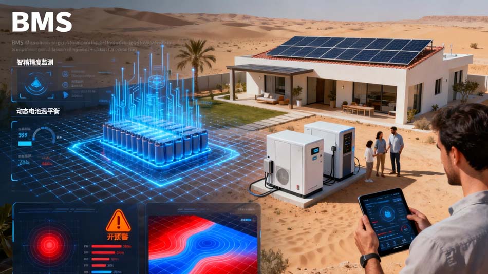
As the new energy vehicle industry evolves toward intelligence and higher integration, the Battery Management System (BMS)—the “central nervous system” of the power battery—directly determines vehicle safety and driving range. Within the BMS hardware architecture, the selection of the main control MCU is especially critical. In recent years, the NXP S32K3 series MCU has become the core choice for a growing number of BMS PCBA solutions, driven by its outstanding performance, functional safety capabilities, and mature ecosystem support. This article examines the key reasons for adopting the NXP S32K3 MCU in new energy vehicle BMS PCBA from the perspectives of technical architecture, safety standards, and engineering practice, using the manufacturing experience of TORTAI Technologies as a real-world case study.
1、Strict Requirements for the Main Control MCU in BMS
A BMS must collect per-cell voltage (accuracy down to ±2 mV), temperature, and total pack current in real time, execute SOC/SOH estimation algorithms, perform cell balancing, and complete fault protection actions (overvoltage, undervoltage, overtemperature) within milliseconds . These tasks demand that the main control MCU possess:
- High-performance real-time processing:handling multiple CAN FD communication channels while running complex algorithms simultaneously.
- High functional safety level:meeting ISO 26262 ASIL C/D requirements .
- Robust information security:preventing firmware tampering and data leakage .
- Rich automotive-grade peripherals:supporting CAN FD, Ethernet TSN, SPI, and other interfaces .
- Wide-temperature stable operation:functioning reliably from -40°C to 125°C .
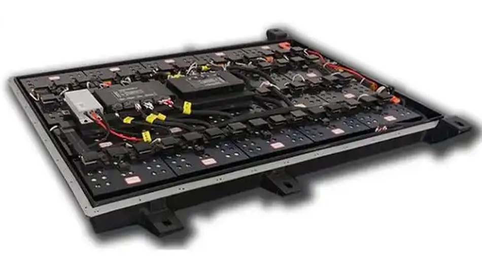
The NXP S32K3 series provides a systematic solution addressing all of these dimensions.
2、Core Technical Advantages of the NXP S32K3 MCU
High-Performance Multi-Core Architecture and Scalability
The S32K3 series is built on the Arm Cortex-M7 core, with a maximum frequency of 320 MHz, and offers single-core, dual-core, and triple-core configurations—including lockstep cores that support ASIL D functional safety . For instance, the S32K312 integrates a 120 MHz Cortex-M7 core, 2 MB flash memory, and 192 KB RAM, and provides 6 CAN FD channels, 4 SPI interfaces, and 2 I²C interfaces . For higher-end BMS applications, the S32K37 series delivers a 320 MHz triple-core configuration to accommodate large-scale cell management needs . This flexible portfolio allows developers to select the optimal chip for their specific BMS complexity while maintaining hardware and software reusability, significantly reducing development cycles .
Top-Tier Functional Safety and Reliability
The S32K3 series is AEC-Q100 Grade 1 qualified and supports ISO 26262 ASIL B/D functional safety levels . Key safety features include:
- Lockstep cores:dual-core redundant operation for real-time instruction consistency checking .
- Hardware Security Engine (HSE):integrated AES-256 and ECC encryption modules supporting secure boot and key management, compliant with ISO 21434 cybersecurity standards .
- Fault Collection and Control Unit (FCCU):performs clock monitoring, voltage monitoring, watchdog supervision, and other fault closed-loop management, capable of detecting 90% of transient faults .
In BMS applications, these mechanisms ensure that every function—from cell data acquisition to high-voltage relay control—is diagnosable and protected .
Rich Automotive Networking and Time-Sensitive Networking (TSN) Support
The S32K3 integrates TSN Ethernet (MAC), CAN FD, LIN, FlexIO, and other automotive interfaces . Its TSN capability supports IEEE 802.1Qbv traffic shaping and 802.1AS/gPTP nanosecond-level time synchronization, providing deterministic communication between the BMS and domain controllers or chargers . In distributed BMS architectures, the Cell Monitoring Unit (CMU) aggregates voltage and temperature data to the Battery Management Unit (BMU) via a daisy chain. The S32K3 can work alongside the NXP MC33665 BMS gateway chip to implement standardized CAN FD communication, replacing proprietary protocols and reducing system complexity .
Mature Software Ecosystem and AUTOSAR Support
NXP provides ISO 26262-certified Real-Time Drivers (RTD) software packages that support both AUTOSAR CP and non-AUTOSAR operating systems . In addition, the S32 Design Studio IDE, MATLAB Model-Based Design Toolbox (MBDT), and safety firmware libraries (SAF) significantly reduce the effort required for low-level driver development, enabling developers to focus on core BMS algorithms .
3、Practical Case: TORTAI Technologies BMS PCBA Based on NXP S32K3
With more than a decade of experience in high-reliability PCBA, OEM, ODM, and EMS services, Dongguan TORTAI Technologies Co., Ltd. has built deep expertise in BMS PCBA manufacturing. The company holds ISO9001:2015, ISO13485, and IATF16949 certifications, adheres to IPC-A-610J CLASS III standards, and operates an MES traceability system.
Case Study: Sodium Battery BMS Control Board PCBA
In a collaborative “cell + PCBA” project between ChuanYi Sodium Battery and KeXiang Technology, TORTAI Technologies customized a dedicated sodium battery BMS control board PCBA. This solution faced the unique voltage platform characteristics of Na⁺ batteries—a per-cell voltage range of 1.5 V to 3.9 V—where detection accuracy in the low-voltage region (<2.5 V) directly affects usable capacity . Leveraging the wide voltage detection capability of the NXP S32K3 MCU , TORTAI Technologies achieved ±2 mV full-range per-cell voltage accuracy, a significant improvement over traditional lithium BMS (±5 mV).
During manufacturing, TORTAI Technologies jointly optimized the buck-boost circuit layout, high-frequency signal integrity, and wide-temperature soldering processes for the S32K3 chip. The results included:
- PCBA yield exceeding 98%
- 20% improvement in energy utilization efficiency
- High-temperature endurance supporting continuous operation at 125°C
This case clearly demonstrates that selecting the S32K3 MCU requires not only the chip’s inherent performance but also the PCBA manufacturer’s capabilities in automotive-grade process control, precision sampling anti-interference design, and full-process traceability.
4、Key Technical Points in BMS PCBA Manufacturing
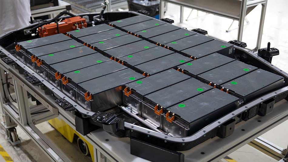
Drawing from TORTAI Technologies’ engineering practice, BMS PCBA manufacturing must address the following critical areas:
High-Voltage Safety and Creepage/Clearance Design
CMU and BJB PCBA operate in 400 V–800 V high-voltage environments. Layout design must ensure adequate electrical clearance and creepage distance between high-voltage networks and low-voltage communication networks, with isolation slots where necessary . Isolation communication chips between high-voltage and low-voltage domains must pass rigorous dielectric withstand voltage testing.
Precision Sampling and Anti-Interference
To achieve millivolt-level voltage measurement accuracy, the resistor divider network around the AFE must use high-precision, low-temperature-drift resistors. PCB traces should employ Kelvin connections to eliminate lead resistance errors. Voltage sampling lines must be routed away from high-current power loops and shielded with ground traces to suppress electromagnetic interference .
Thermal Management and Long-Term Weather Resistance
Passive balancing resistors generate significant heat during operation. The PCBA design must reserve sufficient copper area for thermal dissipation on power resistors. The entire board should undergo selective conformal coating to protect solder joints and exposed traces from moisture and salt spray, preventing insulation degradation.
Full-Process Testing and Traceability
BMS PCBA requires 100% ICT (In-Circuit Test) and FCT (Functional Test) to verify voltage sampling accuracy, balancing drive outputs, communication links, and relay control under simulated real-world conditions. TORTAI Technologies uses its MES system to record material batches, placement parameters, and test results for every board, achieving traceability for over 15 years.
5、Future Outlook: S32K3 in Next-Generation BMS
As sodium-ion battery commercialization accelerates and 800 V high-voltage platforms become more widespread, BMS designs face new challenges and opportunities. The NXP S32K3 series can simultaneously support 400 V and 800 V architectures, as well as switchable 2×400 V/800 V systems . When paired with the MC3377X series Battery Cell Controllers (BCC), it enables scalable cell management ranging from 6 to 18 cells . TORTAI Technologies is also actively developing next-generation BMS PCBA processes: its GaN energy storage inverter PCBA has achieved conversion efficiency exceeding 99%, and its photovoltaic-storage cooperative control board meets automotive-grade reliability standards . These capabilities provide a strong manufacturing foundation for BMS designs in future “X-in-1” integrated architectures (e.g., 3-in-1 to 8-in-1).
Frequently Asked Questions (FAQ)
Q1: Why is the NXP S32K3 series more suitable for BMS than other MCUs?
A: The S32K3 integrates high-performance Cortex-M7 cores, ASIL D functional safety, a Hardware Security Engine (HSE), TSN Ethernet, and rich CAN FD interfaces on a single platform. This provides a “performance + safety + communication” all-in-one solution for BMS, avoiding the complexity and cost of multi-chip combinations .
Q2: What unique advantages does TORTAI Technologies offer in BMS PCBA manufacturing?
A: TORTAI Technologies operates a 4,000 m² modern facility with 4 fully automated high-speed SMT lines. It is IATF16949 certified, adheres to IPC-A-610J CLASS III standards, and participates in customer NPI stage reviews to jointly optimize wide-voltage detection, high-frequency signal integrity, and wide-temperature soldering. Trial production yields exceed 98%.
Q3: How is the long-term reliability of BMS PCBA ensured?
A: Automotive-grade BMS PCBA requires AEC-Q100 certified materials, precision sampling trace design, selective conformal coating, 100% ICT/FCT testing, and full lifecycle management via an MES traceability system . TORTAI Technologies also complies with ISO13485 medical device quality system requirements, further ensuring product consistency.
Q4: What are the main differences between sodium battery BMS and lithium battery BMS in PCBA design?
A: Sodium batteries have a wider voltage platform (1.5 V–3.9 V) than lithium batteries, making low-voltage detection accuracy critical for usable capacity. BMS PCBA requires an MCU that supports a wide voltage sampling range (e.g., S32K3 with a high-precision AFE to achieve ±2 mV accuracy). Sodium batteries also perform better at high temperatures, so the PCBA must be designed for enhanced thermal endurance (e.g., continuous operation at 125°C).
Q5: What capabilities should be prioritized when selecting a BMS PCBA supplier?
A: Key evaluation criteria include: ① Automotive-grade system certification (IATF16949); ② Chip supply chain management capability (e.g., authorized partnership with NXP); ③ Precision soldering and conformal coating process expertise; ④ ICT/FCT test coverage; ⑤ Full-process traceability system; ⑥ NPI stage co-engineering capability. TORTAI Technologies has mature systems across all of these dimensions.
Conclusion
In the new energy vehicle BMS PCBA domain, the NXP S32K3 MCU has become an industry mainstream choice, driven by its high-performance computing, top-tier functional safety, rich automotive network interfaces, and comprehensive software ecosystem . However, the chip’s value is fully realized only through capable manufacturing engineering—from precision sampling layout and wide-temperature soldering processes to full-process testing and 15-year traceability management. Selecting a PCBA partner with proven automotive-grade manufacturing capabilities is equally critical.
If you are planning a BMS project or would like to explore S32K3-based PCBA process optimization, please contact the TORTAI Technologies technical team. We can participate in your NPI stage review and provide one-stop manufacturing services from design review to mass production.