


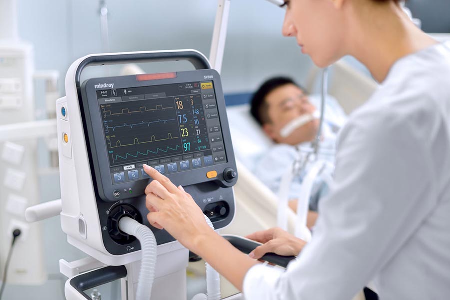
The positive pressure ventilator mentioned here is not the one used by firefighters and rescue workers, but the one used for clinical emergency treatment in hospitals. In clinical practice, it is mainly used to treat sleep apnea syndrome and is also one of the most crucial means to save the lives of critically ill patients. It can automatically monitor the volume of breathing and adjust the pressure value. TORTAI Electronics has rich experience in the design and manufacturing of PCBA boards for positive pressure ventilators and has long provided one-stop manufacturing solutions for small and medium-sized customers in Germany, Italy, Austria, Spain, the United Kingdom, Canada, France, etc.
Core Principles:
High Reliability: The equipment is used for medical treatment, and any malfunction could be life-threatening. The PCBA must have extremely high reliability and stability.
High Precision: The pressure control accuracy is required to be ±0.5 cmH₂O, which imposes extremely high demands on the precision and stability of analog signal acquisition, processing, and motor control circuits.
Low Noise: The operational noise requirement of ≤30 decibels imposes strict requirements on power supply design, component selection (especially motor drive), PCB layout and routing (to reduce EMI), and structural design.
Safety and Compliance: It must comply with medical electrical equipment safety standards (IEC 60601-1 and its -2 specific standards) and electromagnetic compatibility standards (IEC 60601-1-2).
Traceability: From components to finished products, strict records and traceability are required for each stage.
Cleanliness and Protection: Depending on the application environment, the PCBA may need to undergo cleaning, conformal coating, and other protective treatments.
PCBA Processing Information:
PCB Design:
Layer Count: Usually 6-layer or 8-layer boards.
Why do we need multi-layer boards?
Signal Integrity: High-speed signals (such as processor buses, sensor signals) and high-precision analog signals (pressure sensors, flow sensors) require independent, low-interference routing layers and reference planes (GND/Power Plane).
Power Integrity: To provide stable, low-noise power for processors and motor drivers (24V), multiple power planes and good decoupling design are needed.
EMI/EMC Control: Multi-layer boards are easier to achieve good signal return paths, effectively controlling electromagnetic radiation and anti-interference capabilities. Motor drivers and switching power supplies are major noise sources and must be isolated.
Thermal Management: Motor driver chips and power conversion chips generate heat, and inner layer copper foils help with heat dissipation.
Space Optimization: To achieve complex functions within a limited space.
Key Design Considerations:
Partition Design:
High-Precision Analog Area: Signal conditioning circuits for pressure sensors and flow sensors. Needs to be far from digital noise sources and power noise sources. May require an independent ground layer or split ground layer.
Digital Processing Area: MCU/DSP, memory, etc.
Motor Drive Area: H-bridge or three-phase drive circuits for driving brushless DC motors (fans). High current, high dV/dt noise sources.
Switching Power Supply Area: AC-DC or DC-DC converters, high di/dt noise sources.
User Interface Area: Displays, buttons, indicator lights.
Wiring rules:
Analog Signals: Short, straight, with guard traces, away from high-speed digital lines and power lines. Differential routing (if the sensor is differential output).
Digital Signals: Pay attention to impedance control (such as USB, if external), equal length (such as DDR memory), avoid crosstalk.
Power Lines: Sufficiently wide, low impedance. Large copper areas at the power entry point.
High-Frequency/High-Current Lines: Away from sensitive analog lines, avoid parallel long-distance routing.
Grounding Design:
Usually a mixed grounding strategy is adopted: analog ground, digital ground, motor/power ground are connected at a single point (or through magnetic beads/0-ohm resistors), typically at the power input or below the ADC.
A complete ground plane is crucial to avoid poor return paths due to ground plane splits.
EMC Design:
Reserve positions for filter beads and common-mode inductors for critical signal lines.
Reserve shield can pads along the board edge.
Interface circuits (such as power input, sensor connectors, motor connectors) must be designed with filter and protection circuits (TVS, varistors, common-mode chokes).
Heat dissipation design:
Large areas of copper foil are laid under the heat-generating components (motor driver IC, LDO, DC-DC chip) and connected to the heat dissipation layer or to the heat dissipation copper area on the back through heat dissipation holes. Heat dissipation pads or external heat sinks may be required.
Manufacturability design:
Comply with the minimum line width/line spacing, minimum hole diameter, solder mask bridge, and other process capability requirements of the PCBA processing factory.
Component layout takes into account the operability of automatic surface mount and soldering.
Adequate test points are reserved.
PCBA Processing flow (based on medical-grade requirements):
1、PCB manufacturing:
Materials: FR4 TG170 or higher temperature-resistant materials are usually selected to ensure long-term reliability and CAF (conductive anodic filament) resistance. High-reliability applications may require polyimide.
Process: Strict control of deep drilling, copper plating, electroplating, etching, solder mask, and surface treatment.
Chemical nickel-gold plating: Most suitable for medical and high-reliability products. Good flatness, excellent solderability, suitable for fine-pitch components and multiple soldering. Higher cost.
Lead-free hot air solder leveling: Lower cost, thicker pads, but slightly poorer flatness.
Inspection: AOI (automated optical inspection), electrical testing (flying probe/bed-of-nails), impedance testing (for critical circuits).
2、Component Procurement and Management:
Critical! Only use suppliers from the approved supplier list.
Components must be brand new and genuine. Refurbished or used components are strictly prohibited.
Suppliers must provide complete and traceable original factory certificates and batch numbers.
Conduct strict incoming inspection on key components (MCU, sensors, motor driver ICs, power ICs), which may include visual inspection, functional testing, and X-Ray inspection (for BGA).
Comply with the requirements for moisture-sensitive component grade management. Store components in moisture-proof cabinets and control the temperature and humidity in the workshop.
Life cycle management: Pay attention to the life cycle status of key components to avoid using components that are about to be discontinued or have already been discontinued.
3、SMT Assembly:
Steel Mesh Production: Laser cutting is used to create openings based on component types and pad designs.
Solder Paste Printing: High-precision printers are employed to ensure accurate solder paste thickness and placement. Lead-free, low-residue, and no-clean types of solder paste are typically selected.
Placement: High-precision placement machines are utilized, with a high requirement for alignment accuracy. Special attention must be paid to the placement accuracy of fine-pitch components such as BGA and QFN.
Reflow Soldering: Nitrogen-protected reflow ovens are used, with strict control over the temperature profile (preheating, holding, reflow, and cooling) to ensure soldering quality and minimize oxidation and void rates. The temperature profile must be precisely set and continuously monitored based on PCB thickness, component size, and solder paste specifications.
AOI Inspection: Post-soldering, automatic optical inspection must be conducted to check for component presence/absence, polarity, offset, solder bridging, insufficient solder, and tombstoning defects.
4、THT Components:
Wave Soldering: Suitable for through-hole components. Temperature profiles and flux application must be strictly controlled. Selective wave soldering may be required to reduce thermal shock.
Manual Soldering: For components or repair points that cannot undergo wave soldering, certified solderers must use RoHS-compliant/lead-free solder wire.
Visual Inspection/Inspection with Magnifying Glass: THT solder joints must be carefully inspected.
5、Cleaning:
Although no-clean solder paste is used, it is strongly recommended to perform in-line or off-line cleaning after soldering, especially for high-reliability medical devices, to thoroughly remove flux residues, ionic contaminants, and potential solder balls. This can significantly enhance long-term reliability and reduce the risk of leakage current (which affects sensor accuracy). The cleaning agent must be compatible with components and PCBs.
6、Three-proof coating:
Objective: To prevent moisture, mold, salt fog, dust, chemical corrosion, mechanical damage, and to increase creepage distance and electrical clearance. This is particularly important for devices like ventilators that may be exposed to high humidity environments (near humidifiers).
Process: Spraying, brushing, or dipping can be used. Strict masking is required before coating (connectors, test points, heat dissipation areas, sensor areas, etc. should not be coated). The thickness and uniformity of the coating film need to be precisely controlled. Curing should be carried out in accordance with the specifications.
7、Testing:
Online Testing:
ICT: Mainly used to test manufacturing defects (open circuits, short circuits, wrong components, missing components, incorrect values of some components). For complex boards, ICT coverage may be limited (such as analog circuits, high-frequency circuits).
Functional Testing: Crucial! Simulates the actual working environment of the ventilator to conduct a comprehensive functional verification of the PCBA.
Power Supply Testing: Input voltage range (100-240V AC), power consumption, accuracy and ripple noise of each DC voltage output (24V, 3.3V, 5V, etc.) (Ripple noise is a key indicator!) 。
Core Function Testing:
Pressure Control Accuracy Test: Connect a precision pressure gauge (or simulated load), and conduct multi-point tests within the range of 4-20 cmH₂O to measure the deviation between the actual output pressure and the set value, ensuring it meets the ±0.5 cmH₂O requirement. Test the dynamic response and steady-state accuracy in APAP mode.
Flow/Respiratory Monitoring Test: Simulate different respiratory waveforms to verify the accuracy of parameters such as flow and tidal volume monitored by the PCBA.
Delayed Pressure Rise Function Test: Verify the delay time and pressure rise curve.
Alarm Function Test: Simulate scenarios such as mask detachment (large air leakage), power failure, and sensor failure to ensure that alarms are triggered promptly and accurately.
Constant Temperature Humidification Control Test: Verify the temperature control accuracy and stability at each setting (requires cooperation with the humidifier component).
Noise Test: Conduct in a soundproof room or using a sound level meter to verify that the overall noise of the machine is ≤ 30 decibels (usually more accurate after the PCBA, motor, and air duct are assembled).
Data Storage and Transmission Test: Verify that sleep data (usage time, AHI, single event duration, etc.) can be correctly recorded and stored for 365 days, and can be read or exported through the display screen or interface.
Communication Interface Test: Such as USB, Bluetooth, etc. (if available).
Environmental Stress Test: Conduct high and low temperature cycling, high temperature and high humidity storage, etc., at the PCBA or whole machine level to verify environmental adaptability.
FCT: Generally refers to an automated test system that includes some or all functional tests, used for rapid detection on the production line.
Aging Test: Subject a certain proportion of PCBA or whole machines to long-term (e.g., 24-72 hours) power-on aging to expose potential defects in advance (such as poor solder joints, early component failure).
8、Final Inspection, Packaging and Traceability:
All test data must be recorded and archived.
Each PCBA should have a unique serial number or batch number label.
Packaging should be anti-static, shockproof and moisture-proof.
Provide complete production batch records, component traceability information and test reports.
Key Considerations for PCBA Processing (From a Medical Device Perspective):
Supplier Qualification: Select EMS manufacturers that are ISO13485 certified and have extensive experience in processing medical electronic PCBA. Review their quality system, production environment (ESD protection, temperature and humidity control, cleanliness), equipment capabilities, and past medical project experience.
Material Control: This is the cornerstone of the reliability of medical PCBA. It is essential to ensure a transparent and traceable supply chain, with 100% genuine components and complete documentation. Establish a strict incoming quality control (IQC) process.
Process Control: The EMS factory must have strict process control documents, parameter monitoring, and records for all critical processes (solder paste printing, reflow soldering, wave soldering, cleaning, conformal coating).
ESD Protection: The entire production, testing, storage, and transportation processes must meet the highest level of ESD protection requirements (such as ANSI/ESD S20.20).
Conformal Coating: Choose materials that have been verified, have good biocompatibility, and meet medical standards. The coating process must be stable and controllable.
Test Coverage and Rigor: The functional test plan must cover all key performance indicators (especially pressure accuracy, noise, and safety alarms), and test equipment must be calibrated regularly. Testing cannot be a mere formality.
Traceability: Complete traceability must be achieved from PCB batch numbers, component Lot Codes to production dates, operators, and test data. This is a basic requirement of medical device regulations and the foundation for problem analysis and recalls.
Change Management: Any changes in design, materials, or processes must follow a strict engineering change process and be re-validated and confirmed.
Documentation: Require the supplier to provide complete production reports, test reports, bill of materials, process records, and other documents.
Conclude:
The PCBA processing of this positive pressure ventilator is a highly complex and demanding task.
High-precision pressure control: This requires excellent analog circuit design, precise sensor selection, and a processing process that does not damage signal integrity.
Ultra-low noise: Noise sources must be strictly controlled from design (component selection, layout, power supply) to processing (soldering quality, protection).
Medical-grade reliability: This must be maintained throughout the entire supply chain management, production processing, and testing inspection process, and must comply with ISO 13485 quality management system and IEC 60601 safety standards.
Strict testing: A comprehensive functional testing system must be established to ensure that every PCBA leaving the factory meets all key performance parameters.
Selecting an experienced and fully qualified medical electronics EMS partner and investing sufficient resources in design reviews, process validation, and rigorous testing is the key to ensuring the successful mass production and long-term reliable operation of this ventilator’s PCBA.
TORTAI Electronics has served over 27 customers from various regions around the world and has received unanimous praise. We guarantee all-round quality services and also provide DFM manufacturability design solutions for customers, which can reduce the time and cost of product manufacturing and also lower the after-sales service cost of the product. At the same time, TORTAI Electronics has a complete after-sales and logistics team, providing higher quality service tracking for the product.